Conclusion
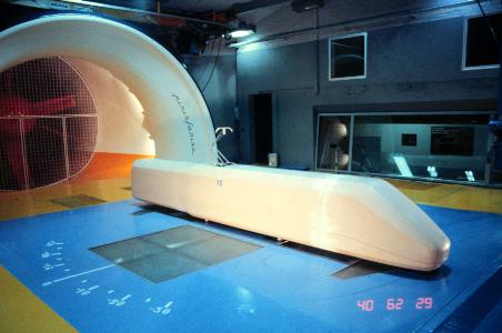
The wind tunnel that was used for this project did not generate the velocities required for the analysis of a high speed train. The CFD analysis performed well and the results produced were what was expected, particularly in reference to the sharp corners at the top of the nose.
No direct comparisons could be made between the two models as the Reynolds numbers were not of the same order.
The small CFD model had a drag force of 4.917e+5 N and the larger model had a drag force of 1.717e+10 N. The ratio between these forces should have been in the order of 50:1 (the same as the model size ratio) but was actually in the region of 35000:1. This clearly illustrates the importance of having the same Reynolds number for the model and the prototype.
|
Recommendations
If a similar project was undertaken in the future the CFD analysis should be concentrated on, with particular attention payed to the post-processing of the results.
Different designs may be compared against each other rather than comparing one shape undergoing both CFD analysis and wind tunnel testing.
Alternatively the size of the model produced could be increased. It is clear that the walls of the wind tunnel were not effecting the model. The region of zero turbulence could therefore be reduced and allow for a larger model to be tested.
|
